Quadcopter Flight Controller
Charlie Lindberg · 2023–2024
Overview
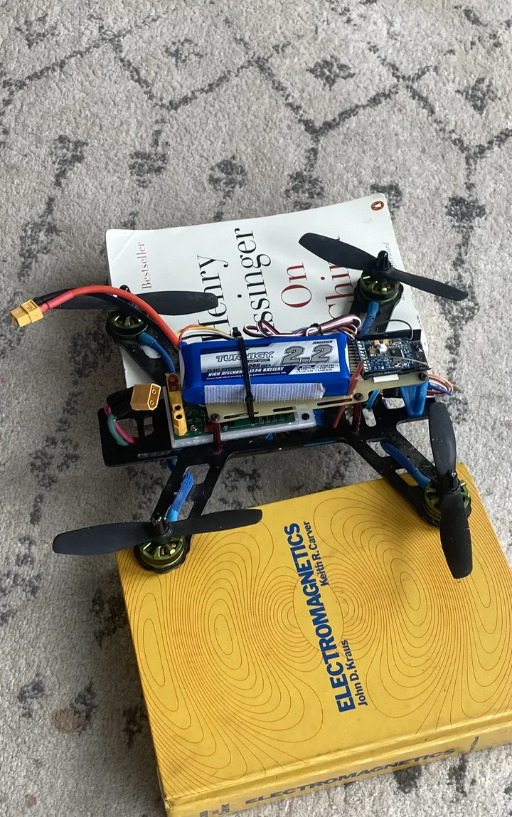
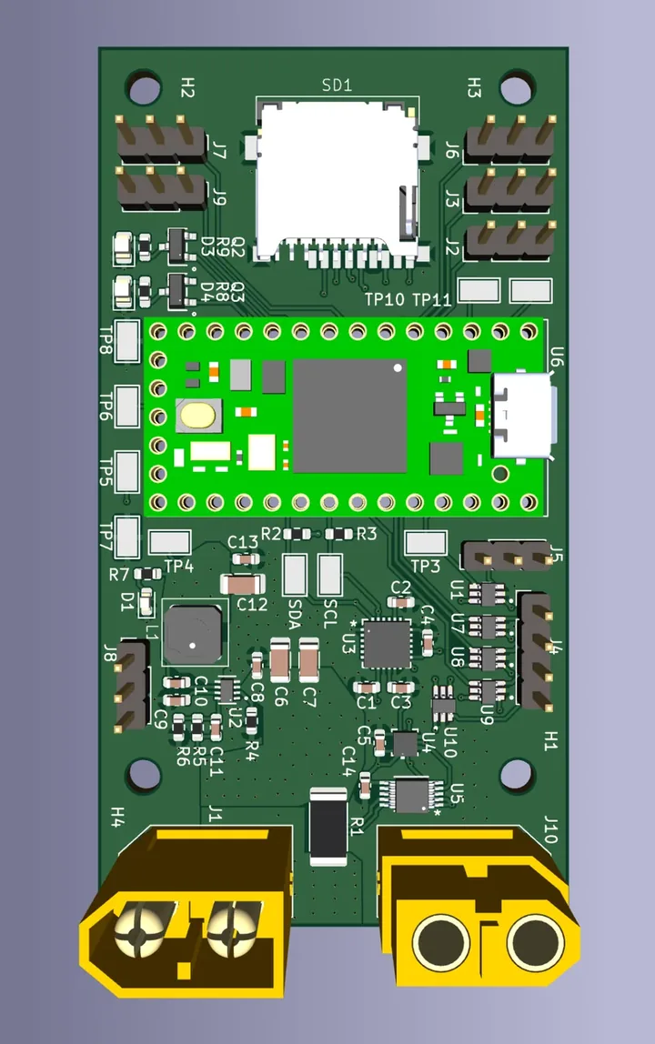
This is a quadcopter flight controller that I designed and built: a custom PCB that carries a Teensy 4.0, an IMU, a barometer, a battery voltage and current monitor, a microSD card for flight logs, and the power and signal circuitry to drive four ESCs from a radio receiver, along with the firmware that flies it.
After finishing my classes in the fall of my senior year, I had about a month of downtime before the spring semester. I decided to revisit a problem I had worked on a few years earlier, designing a flight controller, but this time for a quadcopter instead of a fixed-wing aircraft. It combines several things I enjoy working on: electrical design, control systems and embedded software. I also wanted the board to be platform independent, so it could work across different quadcopters as well as fixed-wing drones.
I chose to include an IMU, a barometer and power monitoring. GPS would have been nice, but I wanted to limit the scope and focus on the controls side of quadcopter flight. After the PCBs were designed, ordered and populated, I integrated the board with the rest of the flight hardware and wrote the software, followed by a painful testing period plagued with software bugs. Eventually it flew decently, although it still struggled in wind and crashes were common.
System architecture
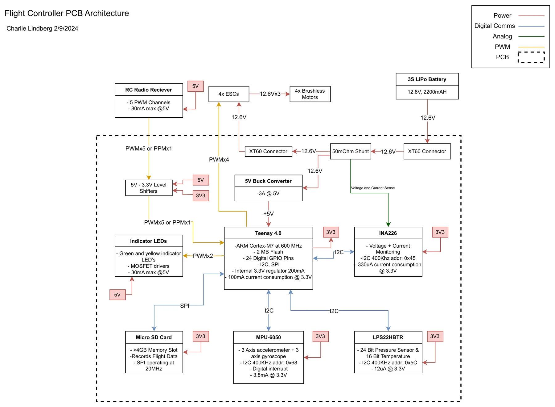
I wanted to keep the board compact while staying flexible enough to work with various ESCs, receivers and batteries. Rather than putting the microcontroller directly on the board, I used a Teensy 4.0 development board. That avoided routing a fine-pitch BGA and the other issues of bringing up a new microcontroller. The Teensy 4.0 is built around an ARM Cortex-M7 running at 600 MHz; I especially liked its speed and wide range of I/O (all GPIOs are interrupt capable, and it has three I2C ports).
Component selection
- IMU. The MPU-6050 (3-axis accelerometer and 3-axis gyroscope) is the key to maintaining level flight. I had used it before and felt comfortable working with it again.
- Barometer. The LPS22HB, a 24-bit pressure and 16-bit temperature sensor. I included it for a possible future feature, but never got around to using it in the control loop.
- Power monitor. The INA226 measures battery voltage and current. I had used it before and liked its accuracy, documentation and simple I2C registers.
- Flight logging. A microSD card slot on SPI, to log flight data for later analysis.
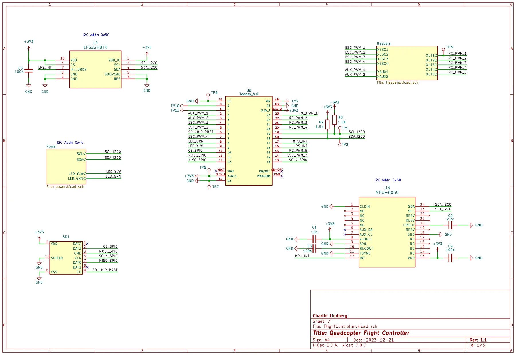
All three sensors have I2C interfaces and share one bus at 400 kHz (addresses 0x68, 0x5C and 0x45).
PCB
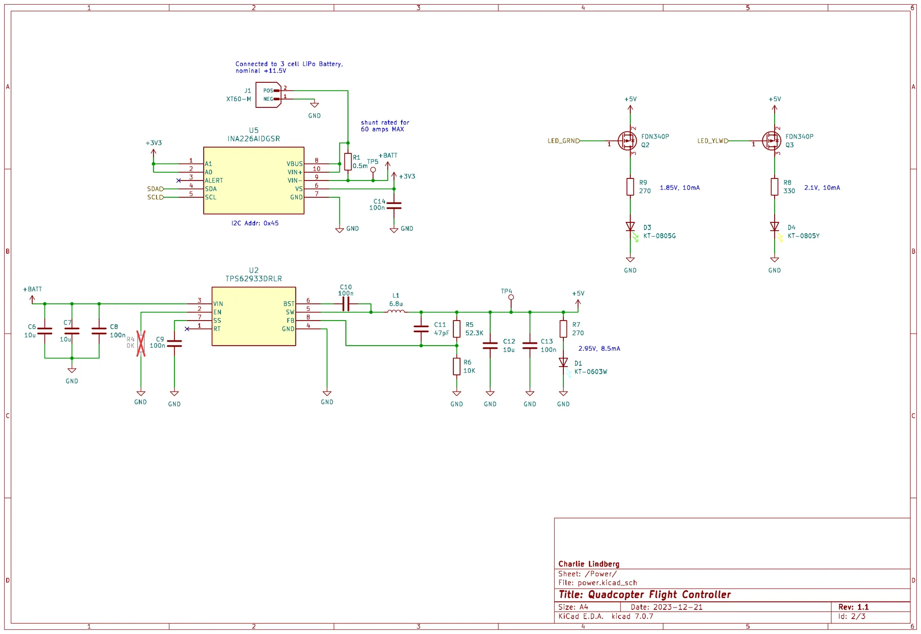
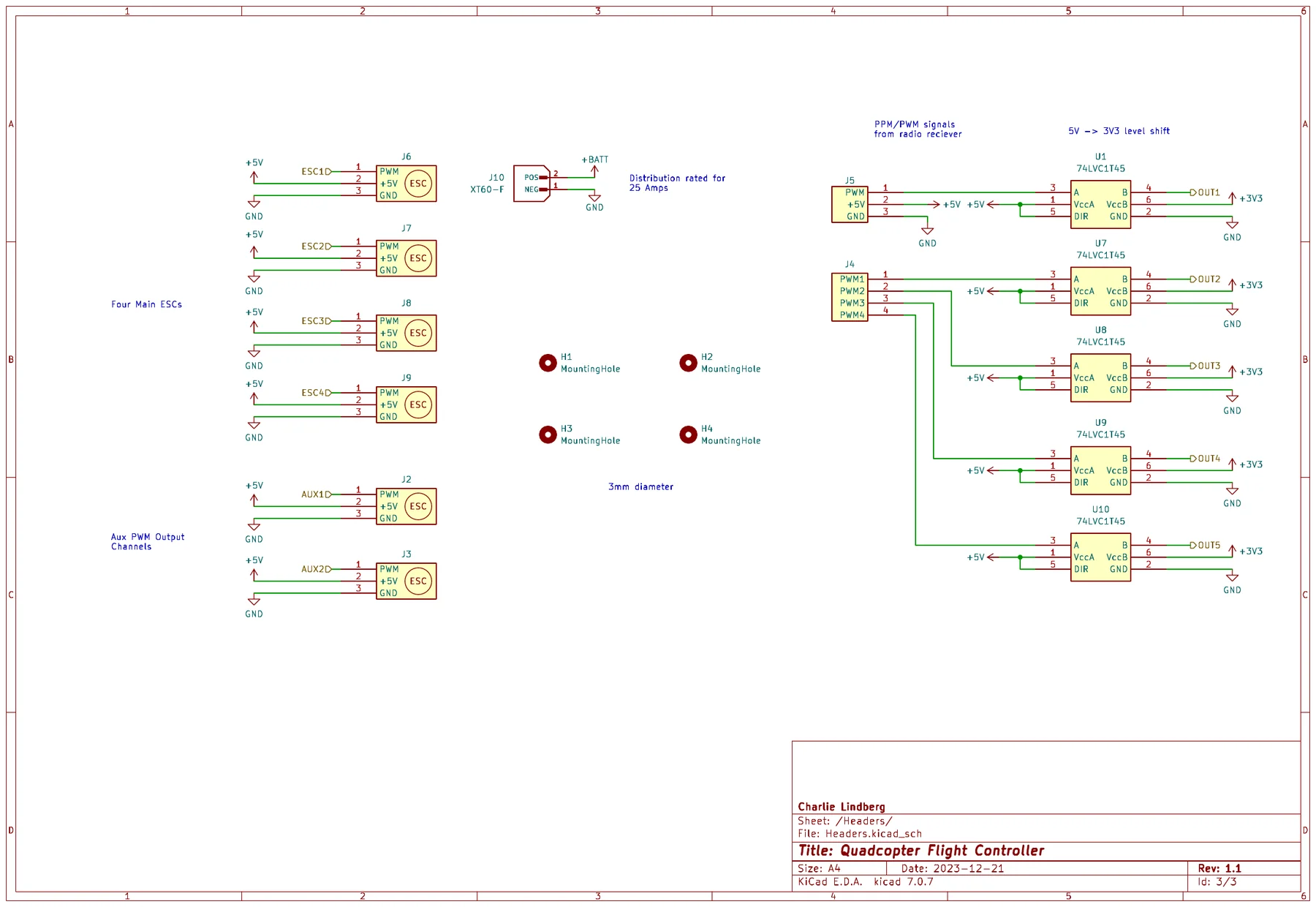
I mostly finished the schematic in December 2023. Besides the Teensy and sensors, the board has a 5 V buck converter (TI TPS62933), green and yellow status LEDs driven by MOSFETs, and five 74LVC1T45 level shifters that convert (if needed) 5 V signals from the radio receiver to the Teensy's 3.3 V logic. The receiver can connect with five PWM channels or a single PPM signal. There are headers for four ESCs and two auxiliary PWM outputs.
To measure current, battery power enters through one XT60 connector, passes through a 0.5 mΩ shunt resistor monitored by the INA226, and leaves through a second XT60 to the ESCs. The output (distribution) XT60 connector is rated for 25 A, which limits the current the board can deliver to the ESCs. This required large power planes, which led to a 6-layer PCB with 1 oz copper throughout. The board measures about 79 × 42 mm.
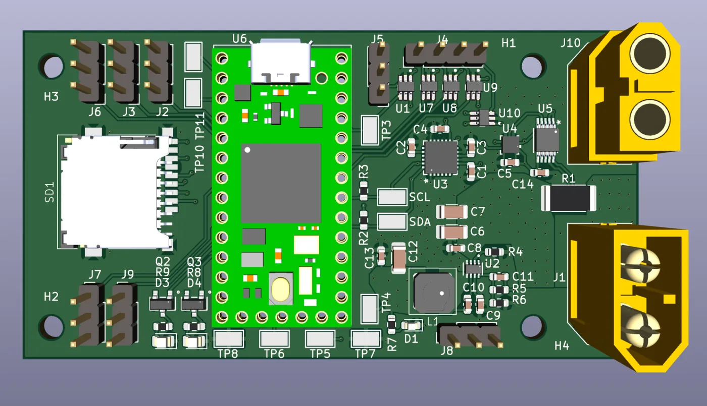
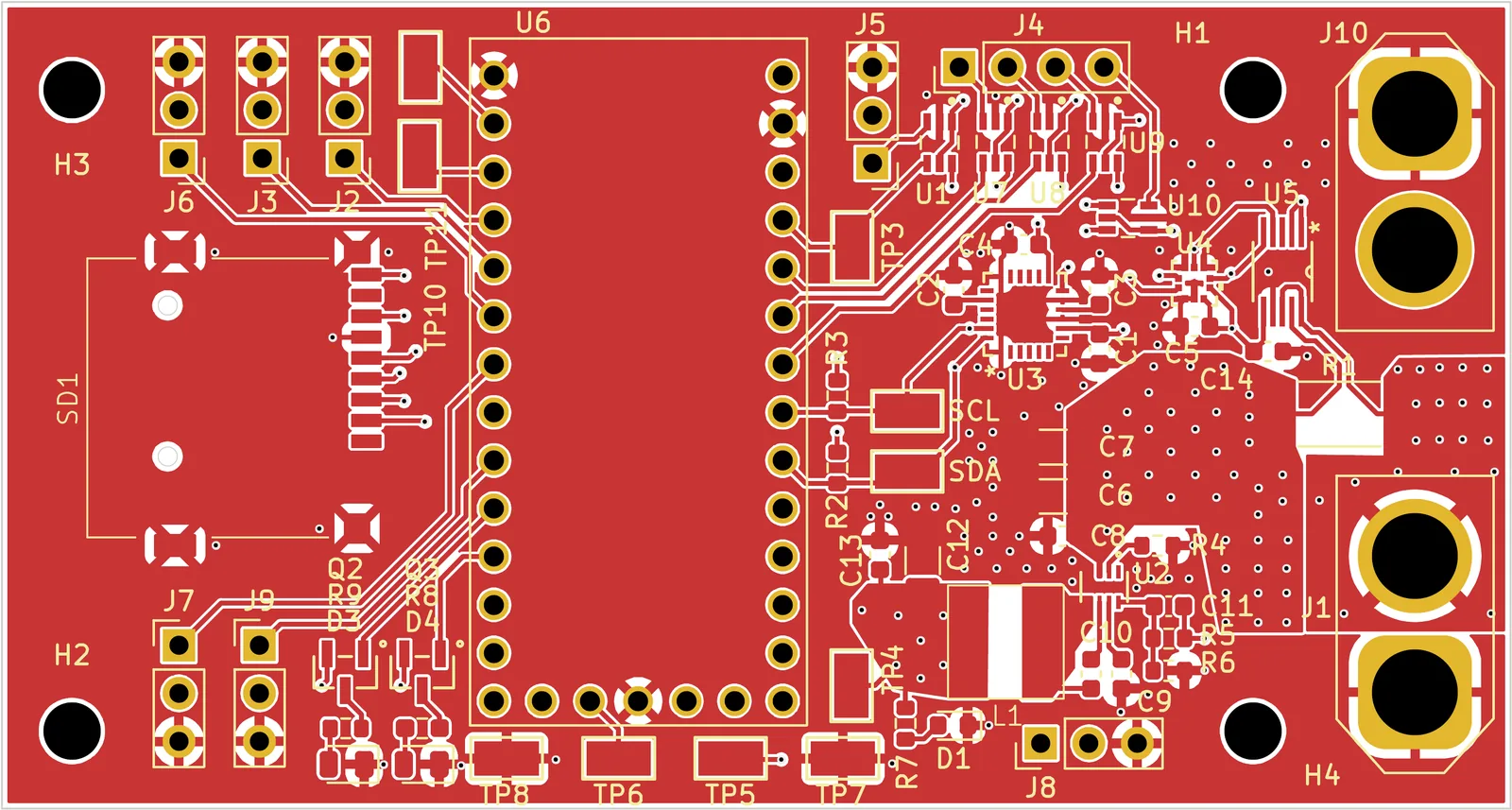
JLCPCB assembled the boards. After they arrived, I tested the basic functionality and connectivity. All peripherals and power circuits worked correctly. The board I flew was this first revision; it never needed a redesign. Once I had written the initial I2C drivers, I was ready to write the overall system software and start testing. View the schematic (PDF).
Schematics
Software
The firmware is a state machine with five states. On power-up, INIT sets up the LEDs, I2C bus and sensors, checks that the board is level, checks the receiver, and waits for the arm switch to be off and the throttle low. In STANDBY, the quadcopter waits to be armed: arm channel high and throttle low. ACTIVE runs the control loop until the arm switch is turned off, then POSTFLIGHT stops the motors, writes the flight log to the SD card and returns to STANDBY. FAULT stops the motors and blinks both LEDs.
Control loop
The ACTIVE state runs every 4 ms (250 Hz). Each loop reads the MPU-6050 and the receiver, runs the roll and pitch PID controllers and the yaw-rate PD controller, mixes their outputs into four motor commands, reads the INA226, and stores a log entry on every fifth loop.
- Attitude estimate. The gyroscope is set to ±500 °/s and the accelerometer to ±8 g. Roll and pitch angles come from a complementary filter (a simplified Kalman filter): the integrated gyro rate weighted 0.98, and the angle from the accelerometer weighted 0.02. Yaw is controlled as a rate.
- PID and PD. Roll and pitch use PID controllers on angle, with the sticks setting an angle setpoint of up to ±25°. Yaw uses a PD controller on yaw rate, with no integral term, and the stick sets a rate setpoint of up to ±25 °/s. The integral term is limited to ±200 and each controller's output to ±500 to prevent saturation.
- Motor mixing. The PID outputs are added to and subtracted from the throttle command (1000–2000 µs) for each motor, then limited before being sent to the ESCs:
| ESC | Position | Command |
|---|---|---|
| 1 | Front right | throttle + roll − pitch + yaw |
| 2 | Back right | throttle + roll + pitch − yaw |
| 3 | Back left | throttle − roll + pitch + yaw |
| 4 | Front left | throttle − roll − pitch − yaw |
Flight logging
During a flight, log entries (timestamp, roll, pitch, yaw rate, battery voltage and battery current) are stored in a linked list in RAM. After the quadcopter is disarmed, the POSTFLIGHT state writes the list to a numbered CSV file on the SD card, with a header recording the PID gains used for that flight, so every log can be matched to its tuning. Battery voltage and current logging was only added later in testing, around flight 175, so earlier logs have no valid power data; flight 183 is the first log with both readings valid.
The firmware is written in C++ for the Teensy (Arduino), split between the main flight loop and a set of drivers for the sensors, receiver, ESCs and SD card.
Quadcopter platform
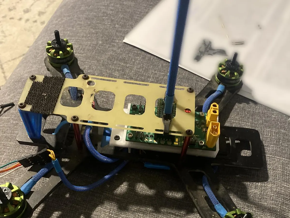
The frame and ESCs were bought off the shelf; the focus of this project was the flight controller, not building the quadcopter. Around the board are a 3S LiPo battery (11.5 V nominal, 2200 mAh), four ESCs driving four brushless motors, and an RC radio receiver.
Tuning, flight results and data
The first flight was in April 2024. The quadcopter flew decently, with my longest flights lasting about 30 seconds. It still had difficulty in wind, and crashes were common.
Because every log records its gains, the flight logs show how the tuning evolved. A selection:
| Flight | Date | Roll P / I / D | Pitch P / I / D | Yaw rate P / D |
|---|---|---|---|---|
| 103 | 5/3 | 2.8 / 0 / 46 | 3.5 / 0 / 72 | 0 / 0 |
| 113 | 5/13 | 3 / 0.0001 / 46 | 3.3 / 0.0001 / 72 | 0 / 0 |
| 120 | 5/14 | 3 / 0.0001 / 46 | 3.3 / 0.0001 / 72 | 1 / 0.5 |
| 141 | 5/18 | 1.8 / 1e-7 / 33 | 1.98 / 1e-7 / 43.2 | 1 / 0.5 |
| 165 | 5/29 | 2.9 / 0 / 35 | 2.9 / 0 / 35 | 0.2 / 0.05 |
| 175 | 5/31 | 2.9 / 7e-7 / 48 | 2.9 / 7e-7 / 38 | 1.2 / 0.6 |
| 186 | 6/4 | 2.3 / 7e-7 / 38 | 2.9 / 7e-7 / 38 | 1.2 / 0.6 |
| 190 | 6/5 | 2.1 / 7e-7 / 38 | 2.9 / 7e-7 / 42 | 1.5 / 0.6 |
| 192 | 6/7 | 1.95 / 7e-7 / 38 | 2.9 / 7e-7 / 42 | 2.5 / 0.6 |
| 197 | 6/8 | 1.85 / 7e-7 / 35 | 2.9 / 7e-7 / 42 | 3.5 / 0.6 |
The final gains (bold) are from flight 190, my most successful flight: one of the longest in the logs at about 23 seconds, with roll and pitch staying within about ±24° until touchdown. Later tuning, including the gains in my last copy of FLIGHT.ino (roll 1.95 / 7e-7 / 38, pitch 2.9 / 7e-7 / 42, yaw rate P / D 3.5 / 0), was intermediate; none of the later logged flights lasted as long.
Lessons learned
I tuned the controllers experimentally: set gains for each axis, fly, watch the behavior in the logs and in the air (oscillation, saturation, or failure to settle), and make small adjustments. Without a good test setup, every test was a real flight, which meant a lot of crashes, a lot of broken hardware, and a very long road to a decent tune.
If I built it again, I'd do one of two things before flying. One is a better test setup that allows quick, repeatable, non-destructive tests of different gains. The other is a proper simulation of the quadcopter's dynamics to find reasonable gains first, leaving only the final tuning for flight. Either would have saved a lot of time and hardware. Controls and dynamics problems like this are just hard.